Two of the more complicated components were always going to be the bladder moulded wingbar corners and the centreboard strut. I put off starting them for as long as I could, but at some point I needed them to progress so I had a coffee and started working out what to do.
I did a bit of research on the web on bladder moulds, and found this guy to be quite helpful. Im sure there are other similar vids but by the time you've watched those, you'll probably have gained all you can and then you have to do an experiment. I had two tests with cheaper materials before biting the bullet and laying up the first part. The first test was pretty hopeless, but by the third attempt I had it down.
The moulds I had finished and prepped earlier, and worked pretty well but in hindsight they could have been stronger to take the fairly serious pressure that they get put under. On one, the MDF split at the join where the two thicknesses of wood had been laminated together, and created a bit of a bump in the finished part. MDF is ok, but probably use a single thickness or glue the sheets together with something better than PVA!
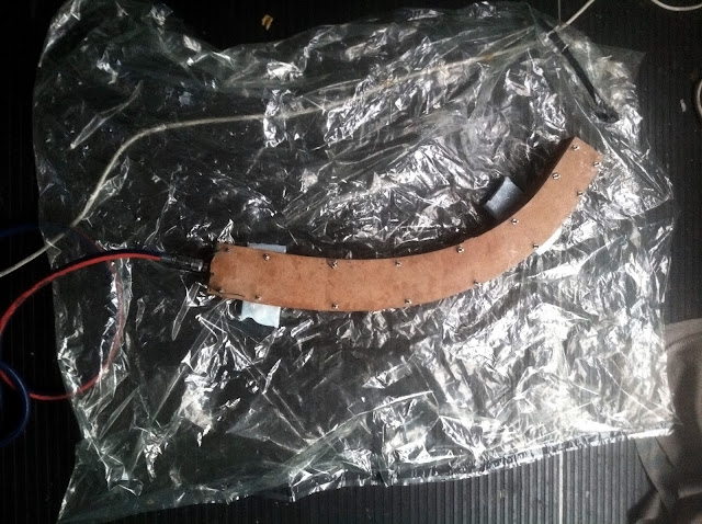
I made bladders as shown in the video, with a soldering iron ground flat at the tip. I went through half a dozen before I got one that would go the distance. I used black builder's plastic, but something more elastic would have given a bit of margin for error - it was too thick and would split before it would stretch. Making it quite oversize seemed to help, with the final size being almost twice the circumference and 100mm longer than the mould. I used a barbed Nitto fitting that plugged straight into the compresser and sealed it to the bladder with a big rubber band as in the vid. A bit of plumbers tape helped, tacky tape was surprisingly useless under positive pressure.
I laid up the tubes so that the carbon in one half was about flush with the seam, and the other half had a 10mm overlap on both sides. That seemed to make it easier to get the bladder in - deflated with the vacuum pump - and then get the carbon to seat cleanly onto the other half when closing the mould. Once closed, I found it could take 40psi without too much drama, and I just left it like that until it cured. Sometimes there would be a slow leak, and the compresser would just cycle as required. That's not ideal, and it's worth getting a good seal.
It's surprising how much more compact the laminate is when cured at 40psi (2.75 atmospheres) compared to under vacuum. The corners came out at about 460g each, but considering how much carbon was in them, that translated to a resin ratio of about 30 - 35% which was on the money I reckon. They are about as bullet proof as I could hope to build. It's a great process.
 |
| The two test runs and the finished product |
 |
| Making the plastic bladder with the soldering iron, baking paper and template |
 |
| The two halves pre-bladder |
 |
| The bladder deflated and held in a bundle with blu-tac. With such a thick laminate it was quite difficult to get it to all sit down long enough to close the mould. |
 |
| The mould closed and under pressure, with resin oozing out of it |
The centreboard was fairly straightforward by comparison, the only difficulties being the meaty layup and the carbon pultrusion that needed to go down the middle. I used standard modulus carbon even though there was some IM available from CG, only because I already had it lying around. I reasoned that the foil section is quite thick at the hull intersection, and that it should be inherently quite stiff, but at the end of the day you can't go wrong with higher modulus material. Next time.
When laying up, I added some extra laminates to build up a flat section for the pultrusion to seat onto. That was all bagged down and in a second step I closed the mould with glue and foaming epoxy inside and let the excess foam spew out a couple of holes. The idea was that as the foam expanded, it pressed the glue into the joints. It seems to have worked, though it's a bit heavier than it could have been - at 250kg/m3 fully expanded, the foaming epoxy isn't as light as a milled foam core, but it is convenient. The whole thing went into the oven for a ~12 hour post cure.
 |
| Making the cutting template from aluminium foil |
 |
| Cutting out the carbon |
 |
| Under Vacuum |


.jpg)


